Learn how industrial CT measures internal cooling channels in additive manufactured parts, including channel size, location, wall thickness, CAD deviation, and defects.
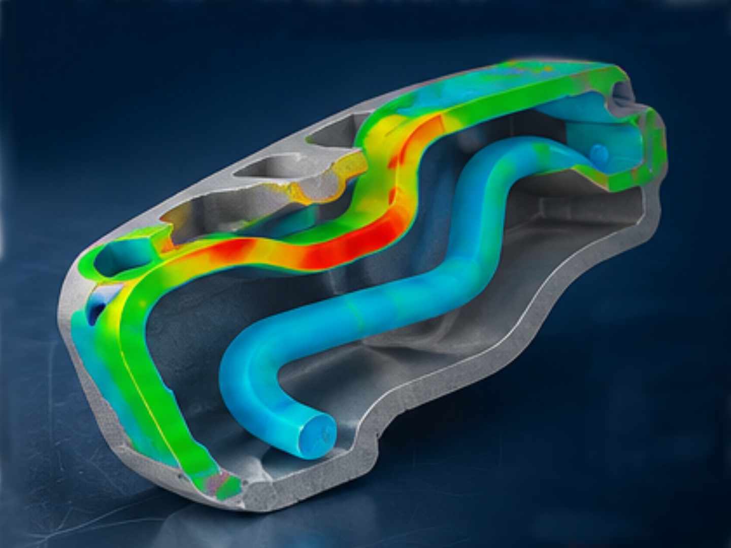
Additive manufacturing opens the door to internal cooling channels that traditional machining cannot provide. That is, conformal cooling channels, serpentine passages, lattice-supported channels - intricacies that find their way into tooling, aerospace parts, heat exchangers, turbines, and thermal management systems.
But here’s the catch. Designing a great internal channel is one thing. Making sure the part you printed actually matches that design is a totally different challenge.
A part can look perfect from the outside, but inside, the diameter could be off. Maybe the path wandered from where you wanted it. The cross-section could be distorted, the wall thickness uneven, or the channel might not even be continuous. Problems like that can alter flow rates, pressure drop, heat transfer, or even the strength of the whole part.
So, how do you measure an internal channel when you can’t actually reach it with a probe or a gauge?
Industrial X-ray computed tomography (CT) scanning offers great potential. This tech gives you a 3D look inside the part, letting you measure the channel and everything around it, no cutting, no guesswork.
But important to note: you don’t just toss the part in a CT scanner and get results. Getting accurate, useful measurements from CT takes real expertise and careful setup. It’s a powerful tool, but only in the hands of an experienced operator.
Traditional dimensional inspection methods work well when the feature being measured is accessible.
A CMM probe can measure an exposed surface. An optical scanner can capture an external profile. A bore gauge can measure an accessible hole.
An internal AM cooling channel can present a completely different challenge.
The channel may:
These characteristics make conventional inspection methods impractical or impossible.
Research into additively manufactured cooling channels has demonstrated that channel geometry, surface condition, build orientation, and manufacturing parameters can all affect the resulting internal geometry. X-ray CT provides a way to characterize these internal features without destroying the part.
That makes CT particularly valuable when the engineering question is not simply “Is there a hole?” but rather:
“What did the manufacturing process actually produce?”
A properly executed industrial CT inspection can provide much more information than a single channel diameter.
Depending on the geometry, resolution, material, and inspection requirements, CT data can be used to evaluate:
The resulting volumetric dataset can also be compared directly with the nominal CAD geometry to identify where the manufactured channel has moved, changed shape, or deviated from design intent.
This is particularly important because external dimensional accuracy does not necessarily predict internal dimensional accuracy in additively manufactured components. Research using CT-based metrology has found that external and internal feature accuracy can behave differently.
The basic CT process is straightforward:
The difficulty is in the details.
For an engineering measurement, the goal is not simply to generate a visually impressive CT rendering. The scan must contain sufficient information to accurately determine the boundary between the solid material and the internal void.
That requires the inspection strategy to be developed around the feature being measured, not simply around the component's overall size.
Before scanning an AM component, an experienced CT inspection team should evaluate several variables.
Material density strongly affects X-ray penetration.
A small polymer component and a dense Inconel component may have completely different scanning requirements even if they have similar physical dimensions.
For metal AM parts, particularly high-density alloys, the X-ray energy, power, filtration, magnification, and acquisition strategy must be appropriate for the material thickness.
The maximum material path through the component affects how much X-ray attenuation occurs.
A complex AM component may have relatively thin sections in one region and substantial material thickness in another. Those variations can affect image quality throughout the scan.
The smallest critical cooling channel often drives the inspection requirements.
A scan optimized to capture the overall geometry of a large component may not provide enough spatial resolution to characterize a small internal passage accurately.
This is one reason scan planning should begin with the critical inspection features and tolerances, rather than simply asking what scanner can fit the part.
A CT scan is a measurement system, and scan parameters affect the resulting measurement.
Important variables include:
Spatial resolution matters, but resolution alone does not guarantee dimensional accuracy.
For example, increasing magnification can improve the effective detector sampling of a small feature, but the usable field of view may become smaller. Similarly, increasing exposure can improve signal quality but may increase inspection time.
The correct settings are therefore a compromise based on the material, geometry, feature size, and measurement requirement.
A high-resolution scan is not automatically a high-accuracy measurement.
That distinction is critical when CT data is being used for dimensional inspection rather than simply visual examination.
Internal cooling channels can be particularly sensitive to CT artifacts because the measurement depends on accurately identifying a material-to-air boundary.
Several phenomena can affect that boundary, including beam hardening, scatter, noise, insufficient penetration, and geometric limitations.
If artifacts distort the channel wall, the resulting measurement can be biased.
For example, a channel may appear slightly smaller or larger than its actual reconstructed geometry depending on the quality of the boundary determination and the local CT conditions.
This is why experienced CT inspection is not simply a matter of selecting a preset scan recipe.
The inspection engineer has to recognize whether an apparent dimensional deviation represents:
a real manufacturing condition, or an artifact introduced by the inspection process.
Once the projections have been acquired, reconstruction software generates the three-dimensional CT volume.
At this stage, the internal cooling channel becomes measurable as a volumetric feature.
The inspection team can create cross-sections perpendicular to the channel, follow the channel through the part, or extract its geometry for comparison with CAD.
For a simple cylindrical channel, measurements might include diameter and location.
For a complex conformal channel, a more useful analysis may involve evaluating the entire channel path.
For example:
Nominal CAD channel → CT-reconstructed channel → 3D deviation analysis
This approach can reveal whether the channel has:
Channel diameter is only one part of the engineering problem.
For many AM cooling applications, the location of the channel relative to the surrounding material is equally important.
Suppose a cooling channel is designed to maintain a specified distance from a functional surface. A channel that is dimensionally correct in diameter but has shifted closer to the surface could produce a significantly different result.
CT allows the channel and surrounding external geometry to be evaluated from the same dataset.
That makes it possible to measure:
This volumetric relationship is one of the major advantages of CT over inspection methods that measure only accessible surfaces.
AM cooling channels are often deliberately designed to depart from simple cylindrical geometry.
A channel might have a teardrop, elliptical, rectangular, serpentine, or other engineered cross-section. It may also change shape along its length.
In these cases, reporting a single diameter can hide important information.
A better inspection strategy may involve taking measurements at defined locations along the channel.
For example:
Measurement
What it tells the engineer
Channel width
Lateral dimensional accuracy
Channel height
Vertical dimensional accuracy
Cross-sectional area
Potential effect on flow capacity
Centerline position
Whether the channel followed its intended path
Wall thickness
Structural separation from adjacent geometry
Channel-to-channel distance
Risk of unintended breakthrough or insufficient material
CAD deviation
Overall conformity to design intent
The appropriate measurement plan should come from the engineering drawing, CAD model, GD&T requirements, or other customer-defined acceptance criteria.
There is another complication with additively manufactured cooling channels: the internal surface is not necessarily smooth.
Powder-bed processes can produce substantial internal surface texture, particularly on surfaces with unfavorable build orientations. Research has shown that internal channel roughness can vary with channel geometry and build direction and can influence flow behavior and pressure losses.
This creates an important distinction between:
Nominal channel size
and
functional flow area.
A channel can have an acceptable nominal diameter while internal surface irregularities reduce the effective flow area.
CT can provide valuable information about the actual three-dimensional internal geometry and, with an appropriate resolution and analysis strategy, can be used to characterize aspects of the internal surface.
However, CT should not automatically be treated as a substitute for a dedicated surface-finish measurement. The resolution and measurement uncertainty have to be appropriate for the roughness scale being evaluated.
This is another reason why inspection planning needs to start with the engineering question.
Dimensional inspection and defect inspection do not have to be separate investigations.
The same CT dataset may reveal internal conditions that help explain unexpected performance.
Depending on the material and scan parameters, CT can identify conditions such as:
NIST research has specifically identified the value of metrological CT for inspecting embedded internal features in metal AM parts because those features can be inaccessible to conventional inspection methods.
This can make CT especially valuable during AM process development.
If a cooling channel is consistently undersized in one region of the build, for example, the CT results can provide manufacturing engineers with evidence that can be correlated against build orientation, thermal history, process parameters, or design assumptions.
The inspection becomes more than a pass/fail check. It becomes process feedback that can help AM engineers identify and refine the manufacturing parameters responsible for dimensional variation.
For a deeper look at how CT inspection results can be used to improve metal additive manufacturing, see [Closing the Loop: Using CT Scanning Feedback to Refine Metal 3D Printing Process Parameters].
The most important point is that scan quality has to be engineered around the measurement requirement.
A good scan should provide enough contrast, spatial resolution, penetration, and artifact control to clearly define the internal channel boundary.
That means the inspection team needs to understand:
A visually clean CT image is not enough.
The question is whether the reconstructed volume supports the specific measurement being reported.
If the cooling channel is accessible and simple, conventional inspection may be perfectly adequate.
But as internal geometry becomes more complex, CT becomes increasingly advantageous.
CT is particularly well suited when:
For AM components, the ability to inspect the internal and external geometry from the same dataset is often the deciding factor.
The real value of CT inspection is not the scan itself.
It is the information the scan gives the engineering team about the relationship between design intent and manufactured reality.
For an additively manufactured cooling channel, that can mean answering questions such as:
Those questions cannot always be answered by looking at the outside of the component.
Industrial CT makes the internal geometry measurable without destroying the part.
For additive manufacturing engineers, that capability can turn CT from a final inspection tool into a source of actionable process information.
At Nel PreTech, we approach CT inspection as a metrology problem, not simply an imaging exercise.
The scan is planned around the material, component geometry, critical internal features, and required measurements. The resulting CT dataset can then be used for dimensional inspection, wall-thickness analysis, internal feature evaluation, defect investigation, and CAD comparison.
For complex AM components, this is particularly valuable because the features that matter most may be the ones that cannot be reached with conventional measurement equipment.
The objective is straightforward:
Produce CT data that is good enough to answer the engineering question with confidence.
Whether the requirement is a handful of critical cooling-channel dimensions or a comprehensive evaluation of the internal geometry, Nel PreTech can help determine the appropriate CT inspection strategy.
Request an inspection quote to discuss your additively manufactured component and the internal features you need to measure.
For complex or inaccessible internal cooling channels, industrial X-ray CT is often the most effective non-destructive measurement method. CT creates a 3D volumetric dataset that allows internal channel dimensions, location, wall thickness, and geometry to be evaluated without cutting the part open.
Yes. CT data can be used to measure internal channel diameter or other cross-sectional dimensions when the scan has sufficient spatial resolution and image quality for the required tolerance.
Yes. Because CT reconstructs the component volumetrically, curved and conformal channels can be evaluated along their three-dimensional path rather than being limited to measurements at accessible openings.
Yes. CT can measure the material between an internal channel and another internal or external surface. This is useful when minimum wall thickness is a critical design requirement.
Yes. A CT-derived representation of the as-built geometry can be compared with the nominal CAD model to identify dimensional deviations, channel movement, distortion, and other differences between design intent and the manufactured part.
CT can detect many internal conditions, including porosity, lack of fusion, cracks, and residual material, depending on the material, defect size, scan parameters, and resolution. The inspection must be designed around the smallest defect of interest.
CT can characterize aspects of internal surface geometry when the scan resolution is appropriate, and research has demonstrated CT-based approaches for characterizing roughness in AM cooling channels. However, CT should not automatically be considered a replacement for a dedicated surface-finish measurement. The appropriate method depends on the roughness scale and measurement requirement.
The dimensional result depends on accurately determining the boundary between the solid material and the internal channel. Factors such as material thickness, X-ray penetration, spatial resolution, noise, scatter, beam hardening, and reconstruction parameters can affect that boundary. A visually good CT image does not automatically guarantee metrologically accurate dimensions.
The most useful information includes the CAD model, engineering drawing, material, part dimensions, critical channel dimensions, tolerances, GD&T requirements, and the specific measurements or defects that need to be evaluated. Providing the engineering requirement allows the CT inspection strategy to be designed around the actual problem rather than simply scanning the part at a generic setting.
Internal cooling channels are one of the applications where additive manufacturing creates inspection challenges that conventional metrology cannot easily solve.
Industrial CT provides access to the geometry that cannot be reached from the outside, but obtaining reliable measurements requires more than high-resolution imaging. The material, geometry, channel size, scan configuration, artifacts, reconstruction, and measurement strategy all affect the final result.
For AM engineers, the goal should not simply be to obtain a CT scan.
The goal is to obtain CT data that can accurately answer the engineering question.

Carter Aldridge is a youthful injection to the Nel Pretech team, bringing a can-do attitude, infectious curiosity, and an out-of-the-box thought process. Carter is one of Nel Pretech’s CT specialists and a Sr. Applications Engineer.


You'll find all the detailed service information you need in one brochure.
Download Brochure
Get a quote within 24-hours and keep your project on schedule.
Get a Quote
Our Nel PreTech engineers are ready to get started on your product challenges.
Ask an Engineer
Download the ultimate CT Scanning Buyer's Guide to improve understanding, time, and efficiency in your scanning needs. Over 50 Pages of useful data and case studies.
Download Now