See how industrial CT scanning inspects medical device fluid paths, checking blockages, wall thickness, and alignment without cutting devices open.
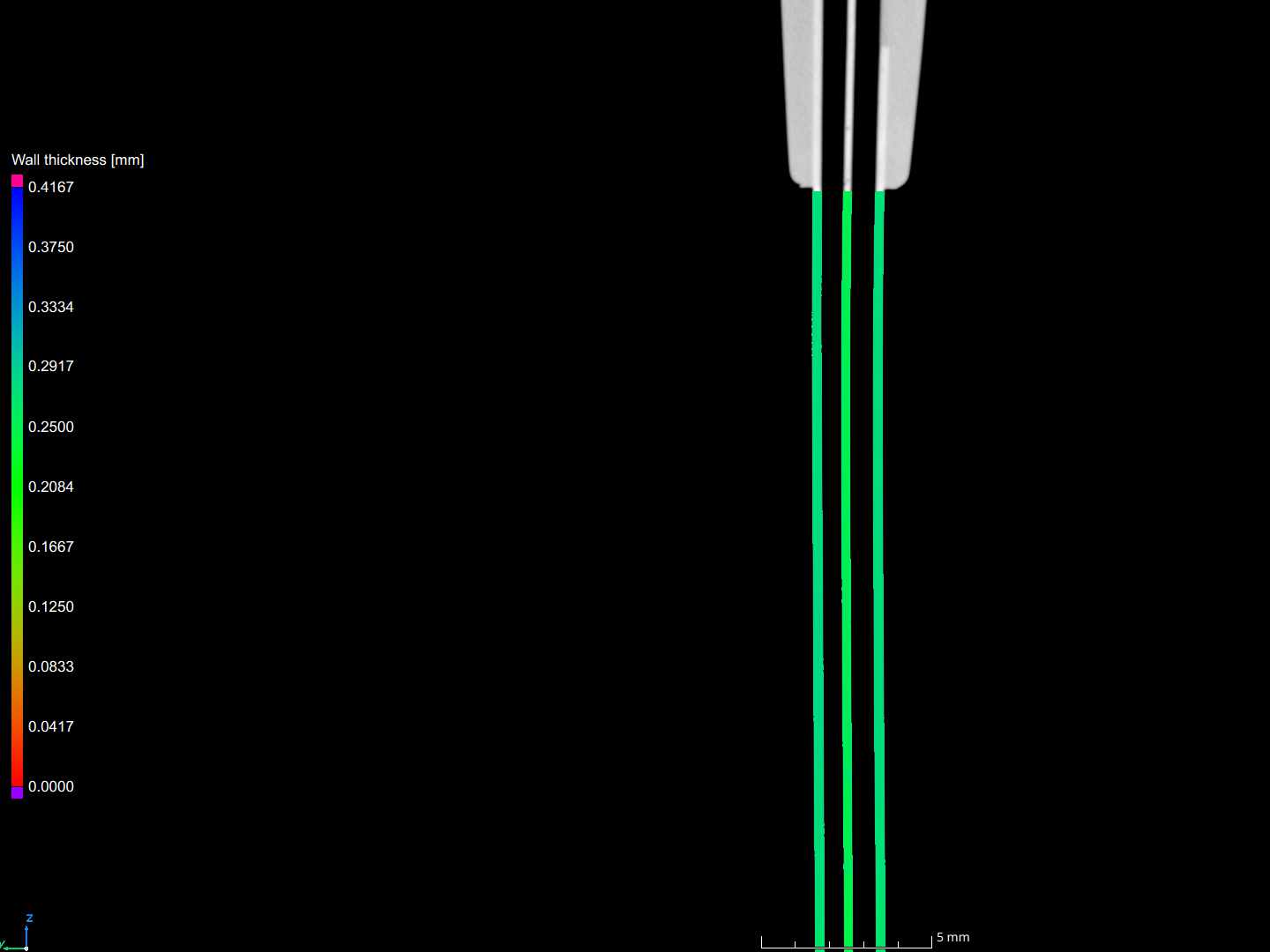
Yes. Industrial CT can inspect internal fluid-flow paths without cutting open the device. CT reconstructs the internal geometry of a medical device in 3D, allowing engineers to inspect passage continuity, measure internal dimensions, identify obstructions or misalignment, evaluate wall thickness, and compare the manufactured geometry with CAD—all while preserving the assembled device for further testing.
In this article, fluid path refers to the internal lumen, channel, bore, passage, or interconnected volume through which a liquid or gas is intended to travel.
When a pump delivers less fluid than expected or a catheter shows unexpected pressure loss, the problem can sit deep inside the device where gauges, cameras, and CMM probes cannot reach.
A molded channel can neck down. Flaws can extend into a manifold passage. A Luer bore can shift off-center. Two internal ports can miss their intended alignment after assembly. A reduction in passage diameter or cross-sectional area can increase flow resistance and pressure drop, depending on the fluid, passage geometry, flow regime, and operating conditions.
FDA recalls and guidance illustrate why internal flow-path geometry can matter to device performance. For example, FDA has documented infusion-system manufacturing variations that partially occluded tubing and resulted in under-delivery, while FDA catheter guidance addresses both pressure capability and clinically acceptable flow rates.
For medical device fluid path inspection, industrial computed tomography (CT) gives engineers a way to study the geometry behind those problems while preserving the device in its assembled condition.
Cutting or disassembling the device can change the evidence you're trying to investigate.
For example, sectioning may:
Industrial CT provides a way to inspect the internal geometry while preserving the device for additional analysis when the application and scan requirements permit.
A fluid path rarely needs to be completely closed before it becomes an engineering concern.
In catheters, manifolds, pumps, inhalers, IV components, and drug-delivery devices, engineers can use CT data to follow a lumen or passage through the full 3D volume. Cross-sectional views can show where the opening becomes smaller, changes shape, or stops unexpectedly.
With industrial CT scanning services, the reconstructed surface can also be measured. Depending on scan capability and the required tolerance, engineers can evaluate bore diameter, cross-sectional area, channel position, and the smallest opening along a passage.
This gives the team more useful information beyond confirming that a hole or defect exists.
Obstructions can come from loose material, an incorrectly positioned seal, an insert that shifted during molding, or one component intruding into another component's flow path.
This is where CT scanning for internal assembly analysis provides extra value.
The device stays assembled while the scan captures the relationship between its internal parts. Engineers can move through the volume slice by slice, identify where an obstruction begins, and measure its position relative to nearby features.
That can help separate a molding problem from an assembly problem.
A recent Luer assembly project also shows why this matters. CT captured hidden spin-collar features, threads, internal interfaces, and assembly relationships in one dataset without disassembling the device.
The fluid passage itself tells half the story. The material surrounding it matters too.
Core shift in an injection mold can move the internal channel closer to one side of the part. The opening can remain clear while one wall becomes much thinner than the design intended.
As a non-destructive testing method, CT-based wall-thickness analysis maps the distance between internal and external surfaces across the part without cutting it open. Engineers can identify minimum-wall regions, uneven wall distribution, and areas where the passage has shifted relative to the outside geometry.
CT's ability to measure inaccessible internal features does not eliminate measurement uncertainty. Scan setup, resolution, X-ray penetration, surface determination, material properties, reconstruction, and the measurement strategy all influence the result. NIST research on CT dimensional measurement emphasizes the importance of controlling and evaluating these factors.
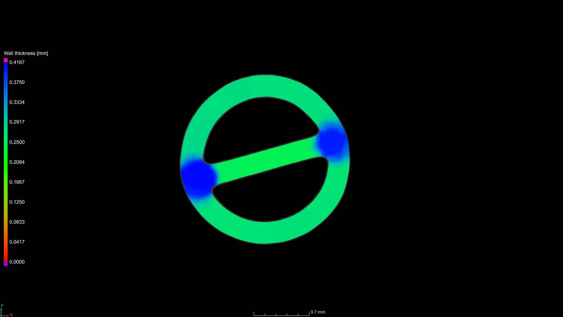
Complex molded devices often contain intersecting channels and junctions that are hard to inspect from either end.
A manifold can have several passages that should meet at one junction. A Luer connector can require precise bore alignment. A pump or inhaler can depend on several molded and assembled parts creating one continuous path.
CT data can be registered to the nominal CAD model so engineers can evaluate both the internal passage and the surrounding manufactured geometry. Color mapping can reveal dimensional deviation, while sectional views and individual measurements can quantify specific features such as bore diameter, wall thickness, port position, and alignment.
For assembled devices, the CT dataset can also show whether components are positioned as intended relative to one another.
Porosity analysis can also identify detectable voids near the fluid path. The location matters. A pore near a thin wall deserves different engineering attention than one buried in a thick, noncritical region. A visible pore by itself does not establish that a leak path exists. CT can identify detectable voids and their location, but whether a void creates a through-wall leak path depends on its size, orientation, connectivity, surrounding geometry, and the material and pressure conditions involved.
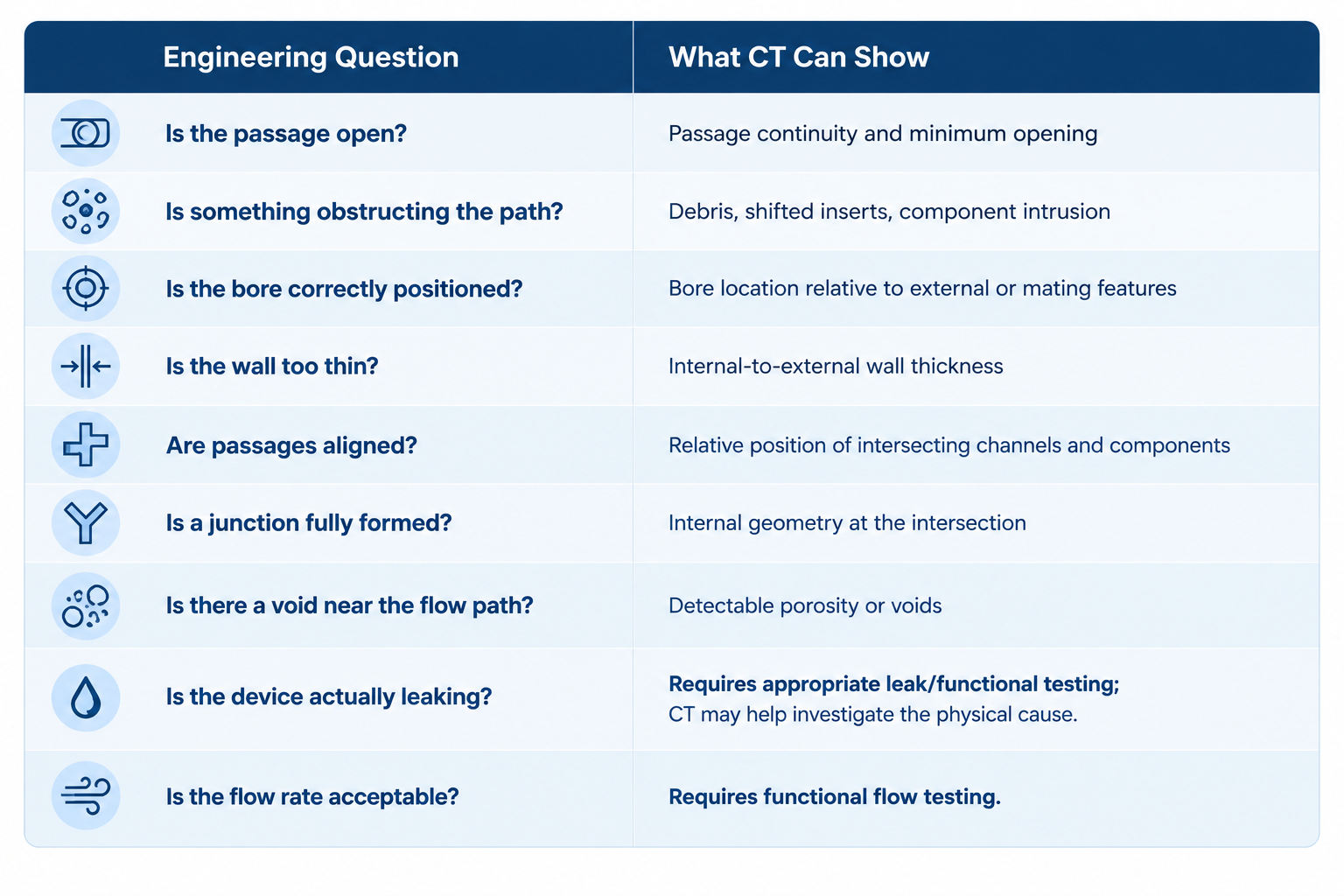
CT and medical device leak testing answer different questions.
CT explains geometry. It can locate a restriction, misalignment, thin wall, void, or malformed passage.
Leak, pressure, and flow tests evaluate performance under defined conditions. FDA catheter guidance, for example, discusses both pressure capability and clinically relevant flow-rate testing.
That makes the methods especially useful together. A functional test can show that flow or sealing performance is outside the expected range. CT-based non-destructive evaluation can then help engineers investigate the physical geometry behind the result.
For small-bore connectors, the ISO 80369 series addresses dimensional and functional requirements. ISO 80369-7:2021 specifies requirements for intravascular and hypodermic small-bore connectors, including Luer connectors, while ISO 80369-1:2025 establishes general requirements for the series. CT can be used as an engineering inspection method to evaluate the manufactured geometry of these features; compliance still depends on the applicable standard, test method, and acceptance criteria.
CT may not be the appropriate primary method when:
The most effective inspection plan may combine CT with CMM, optical measurement, leak testing, pressure testing, or flow testing rather than relying on a single method.
For example:
Determine which passages, junctions, seals, interfaces, or dimensions may influence performance.
Preserving the assembly can be particularly important when component position or interface alignment is part of the suspected problem.
Generate cross-sectional views, 3D volume renderings, and/or surfaces as appropriate.
Examples:
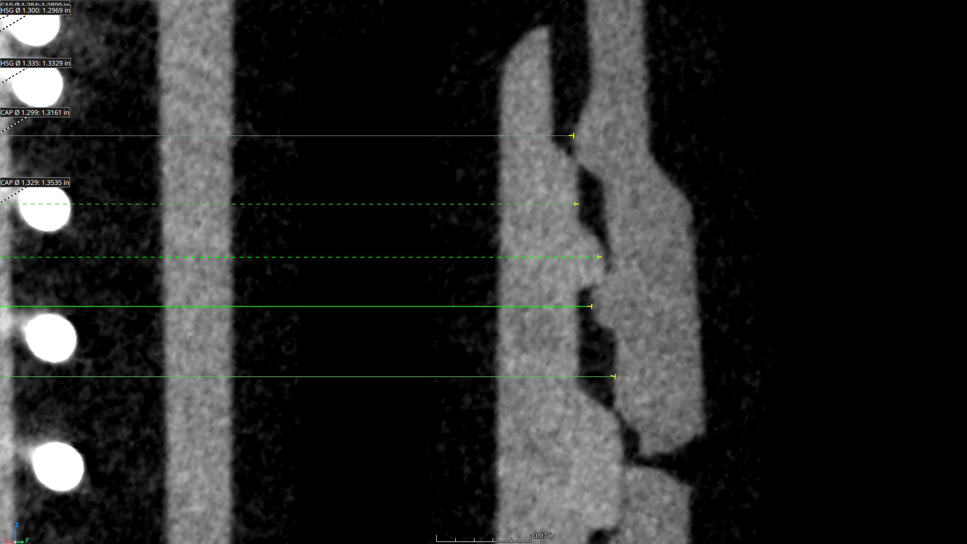
Use sectional measurements, deviation analysis, or color mapping where appropriate.
Use the CT evidence to investigate whether the observed geometry could plausibly explain the functional result.
The goal of CT inspection is not simply to produce an image of the inside of a medical device. It is to establish whether the manufactured geometry provides evidence that can explain a functional result.
When a device exhibits unexpected flow, pressure, leakage, or obstruction behavior, CT can preserve the assembly while giving engineers access to otherwise inaccessible internal geometry. Combined with dimensional analysis and appropriate functional testing, that information can help distinguish a geometry problem from a material, molding, assembly, or performance issue.
Have a medical device that is failing a flow, pressure, or leak test?
Nel PreTech can use industrial CT and dimensional analysis to investigate the internal geometry without sectioning the device. Provide the device, available CAD data, functional-test results, and inspection requirements, and the engineering team can develop an inspection approach around the specific question.
No. Industrial CT characterizes the internal geometry of the fluid path. Flow rate, pressure drop, and leakage require appropriate functional testing. CT can help identify geometric conditions that may explain those results.
Yes. One of the primary advantages of industrial CT is the ability to inspect internal geometry within an assembled component without physical sectioning.
Yes, when the obstruction and surrounding materials are sufficiently resolved in the CT dataset. Examples include molding flash, shifted inserts, misplaced components, and material intrusion.
Yes, provided the feature, scan conditions, material, reconstruction, surface determination, and measurement uncertainty support the required measurement.
CT can identify geometric conditions associated with potential leak paths, such as voids, cracks, wall-thickness variation, or misalignment. It does not replace a functional leak test for demonstrating leakage under defined conditions.
Yes. CT can characterize internal bores, threads, interfaces, alignment, and other inaccessible geometry in Luer assemblies. ISO 80369-7:2021 addresses dimensional and functional-performance requirements for intravascular and hypodermic small-bore connectors.
Yes. CT datasets can be registered against nominal CAD geometry to evaluate dimensional deviation and internal feature position.

Carter Aldridge is a youthful injection to the Nel Pretech team, bringing a can-do attitude, infectious curiosity, and an out-of-the-box thought process. Carter is one of Nel Pretech’s CT specialists and a Sr. Applications Engineer.


You'll find all the detailed service information you need in one brochure.
Download Brochure
Get a quote within 24-hours and keep your project on schedule.
Get a Quote
Our Nel PreTech engineers are ready to get started on your product challenges.
Ask an Engineer
Download the ultimate CT Scanning Buyer's Guide to improve understanding, time, and efficiency in your scanning needs. Over 50 Pages of useful data and case studies.
Download Now