The Challenge: Hidden Failures in Complex Manufacturing Methods
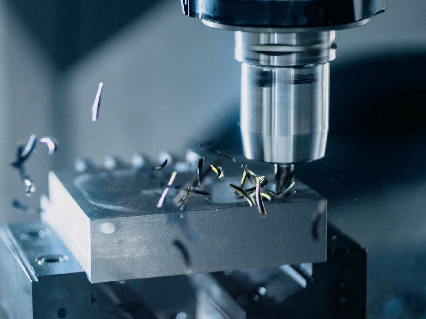
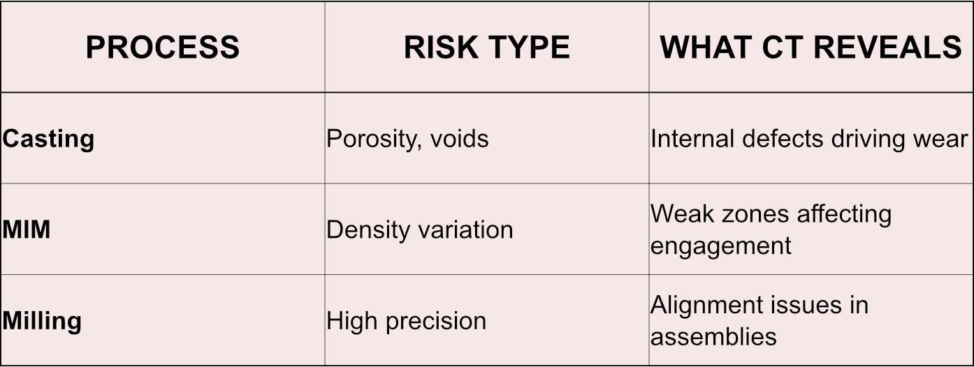
In manufacturing, simply measuring surfaces or checking dimensions may not be enough. Engineers need to see what’s really going on inside-how parts fit together, where fatigue might be present, or why the parts fail unexpectedly in real-world scenarios. Each manufacturing process-casting, metal injection molding (MIM), or precision machining-comes with its own distinctive set of risks and performance-related issues. Industrial CT scanning digs in and reveals what is happening beneath the surface. It is a modern scanning technology that projects a low-energy X-ray beam onto a sample. A detector gathers 2D slices, and the tomographic data is reconstructed to form a complete, accurate 3D model to expose volumetric root causes.
Casting: The Problem of Hidden Failures
Typical Failure Mechanisms
Cast components are intrinsically susceptible to:
Gas porosity and shrinkage voids
Inclusions (slag, oxides)
Segregation and non-uniform cooling
Hot tearing and micro-cracking
These defects can hide undetected. This means the part can pass visual inspection and even dimensional surface checks while carrying underlying risk.
What CT Scanning Reveals
CT provides true volumetric defect characterization, not sampling.
Engineers can identify:
Void distribution and size (critical for fatigue life prediction)
Defect clustering in high-stress regions
Connectivity of porosity networks (key for crack propagation)
Wall thickness inconsistencies tied to solidification issues
Real-World Applications: Where CT-Based Wear and Engagement Analysis Delivers
This capability becomes most valuable in assemblies where internal contact, load transfer, and lifecycle behavior determine performance—not just nominal dimensions.
Aerospace and Defense Assemblies
Use case: Gear trains, actuator housings, turbine-adjacent components produced via casting or hybrid processes
What’s evaluated:
Subsurface porosity in load-bearing regions
Gear tooth contact patterns and alignment
Wear progression after duty cycles or qualification testing
CT advantage: Non-destructive validation of internal defects + engagement behavior in a single dataset, supporting FAI and ongoing reliability programs
Medical Device Components (High-Precision, Regulated)
Use case: MIM-produced components, micro-features, and tight-tolerance assemblies (e.g., connectors, delivery mechanisms)
What’s evaluated:
Density variation and fine porosity at functional interfaces
Thread engagement, sealing surfaces, and mating geometry
Post-use wear or deformation in validation testing
CT advantage: Correlates microstructural variation → functional performance, while supporting traceability and compliance documentation
Automotive Drivetrain and Powertrain Systems
Use case: Cast housings, gears, shafts, and multi-component assemblies under cyclic loading
What’s evaluated:
Porosity-driven fatigue risk in cast parts
Contact patterns between gears and bearings
Wear distribution after endurance testing
CT advantage: Identifies failure precursors before catastrophic breakdown, enabling design and process adjustments early in development
Additive + Hybrid Manufactured Components
Use case: AM parts integrated with machined features or legacy components
What’s evaluated:
Internal defects unique to additive processes
Interface alignment between printed and machined geometries
Wear behavior at hybrid junctions
CT advantage: Bridges the gap between complex internal geometry and real-world assembly performance
Industrial Equipment and Legacy Systems
Use case: Obsolete or long-life machinery with unknown wear history
What’s evaluated:
Degradation patterns in critical interfaces
Internal damage without disassembly
Reverse engineering of worn geometry vs. original condition
CT advantage: Enables non-destructive lifecycle assessment, supporting maintenance, redesign, or part replacement strategies
Business Impact: Turning Inspection into Engineering Insight
CT-based wear and engagement analysis moves inspection beyond pass/fail and into actionable decision-making.
Faster Root Cause Analysis Identify failure mechanisms quickly by linking internal defects, alignment issues, and wear patterns in a single dataset.
Reduced Field Failures Detect failure precursors early and validate real assembly behavior, lowering warranty risk.
Smarter Design Iteration Compare as-designed, as-built, and as-worn conditions to refine tolerances, materials, and geometry.
Process Optimization Tie defects directly to casting, MIM, or machining variables to improve consistency and reduce scrap.
Less Destructive Testing Replace teardown with repeatable, non-destructive analysis, saving time and cost.
Stronger Compliance Support Deliver traceable, audit-ready data for FAI, PPAP, and regulated environments.
The bottom line is, CT scanning can answer how a part performs over time and why it fails. If you are looking for actionable 3D data to solve product failures, contact the scanning service experts at Nel PreTech Corporation.
Victoria is the Creative Marketing Manager at Nel PreTech Corporation. She takes complex topics, like industrial CT scanning and 3D engineering, and turns them into accessible content for engineers and decision-makers. With a strategic communication background, she's helped Nel PreTech become a go-to partner in precision measurement and digital manufacturing. Off the clock, you’ll probably find her on a snowboard or hunting down the best tacos in town. She's not afraid to carve her own path!
Social Media:
Get great content to your inbox.
Thank you! Your submission has been received!
Oops! Something went wrong while submitting the form.
Let's get started solving your 3D & CT Scanning Challenges
Download a Brochure to See What's Possible
You'll find all the detailed service information you need in one brochure.
Download the ultimate CT Scanning Buyer's Guide to improve understanding, time, and efficiency in your scanning needs. Over 50 Pages of useful data and case studies.