Learn how layouts are created, and when CMM, CT scanning, 3D scanning, or vision measurement can provide the right data.
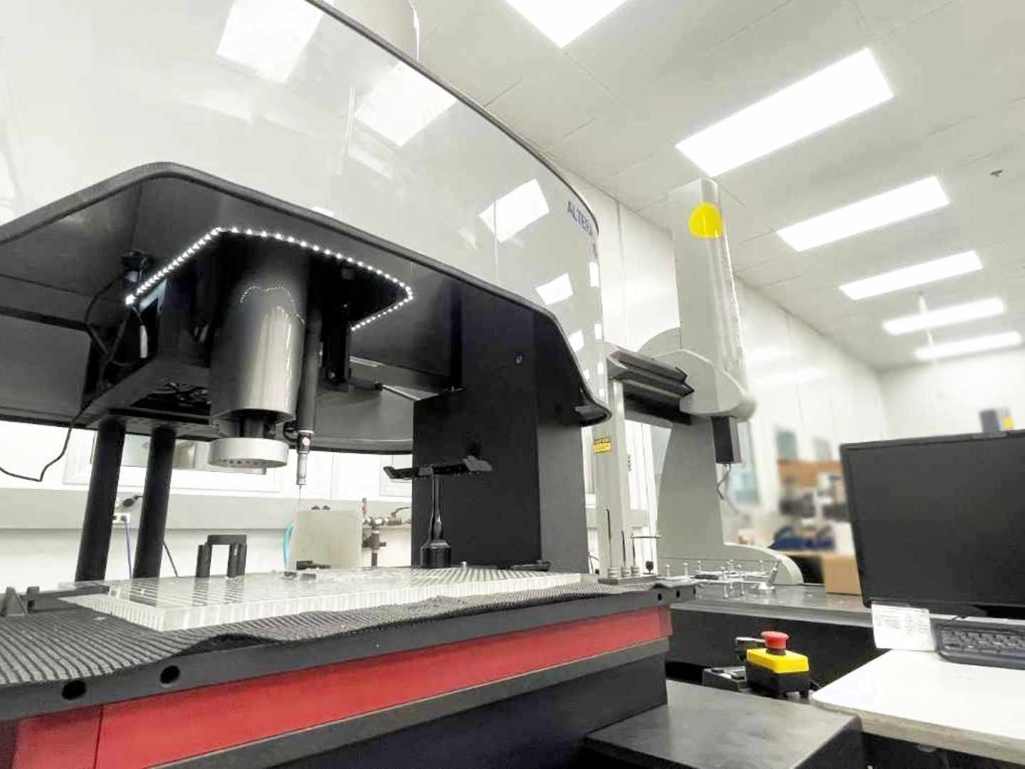
Let’s say you have a part in hand. On the surface, everything seems fine, but you know something is off. Maybe a hole isn’t quite where it should be. The outside dimensions may be good, but something inside the part isn’t lining up. This is where a dimensional inspection layout comes in.
At its core, a dimensional inspection layout is a measurement report. It compares what you actually measured on the part to what you were supposed to get—drawing callouts, CAD data, or any other requirement you’re working to. This info gives engineers and quality teams the details they need to judge a part—not just guess.
Straightforward? Sure. However, to make a layout useful, you need to think about:
Which features need to be measured? How should the part be aligned? Is a CMM the right tool? Would CT scanning show you something you’d otherwise miss?
What's in a Dimensional Layout Report?
Reports can vary, but a typical dimensional inspection layout covers the basics:
● Part number and revision
● Drawing or CAD revision
● Inspection date
● Equipment and method used
● Datum structure
● Nominal dimensions and tolerances
● Actual measured values
● Deviation from nominal
● Pass/fail or in/out-of-tolerance data
● GD&T characteristics
● Inspection notes
If you’re using CMM inspection, expect to see hole diameters, slot widths, or distances between surfaces.
With industrial CT scans or 3D scans, you’ll get analysis that draws on a much larger set of measured geometry.
Bottom line? The report should focus on what matters most for the job. A layout isn't automatically comprehensive because it contains a lot of data.
At Nel PreTech, the test report outlines several important and easily accessible pieces of information: What tools were used, what the measurement uncertainty is on all of our equipment, lab temperature/humidity, measurement results, in/out spec condition, and final inspection sign-off for an added layer of security.
Additionally, a coversheet is included to supplement the test report. It provides information that might be helpful to better understand part or feature conditions. At a minimum, it will describe how the part was set up for measurement, how the alignment system was created with or without the aid of print datums, and any comments that might provide better clarity for the measurement results.
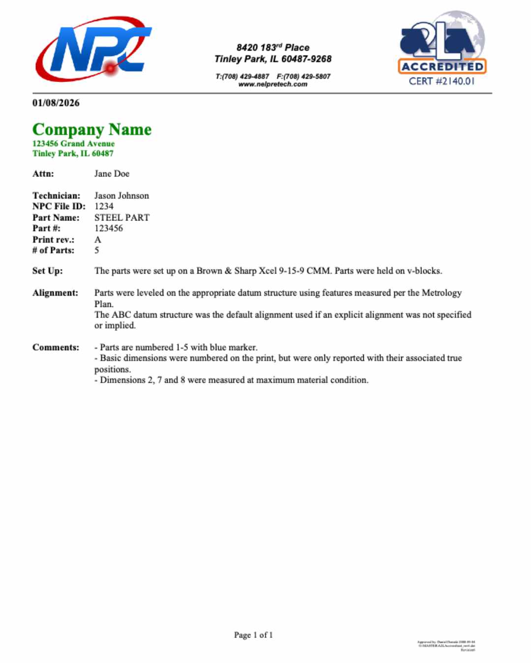
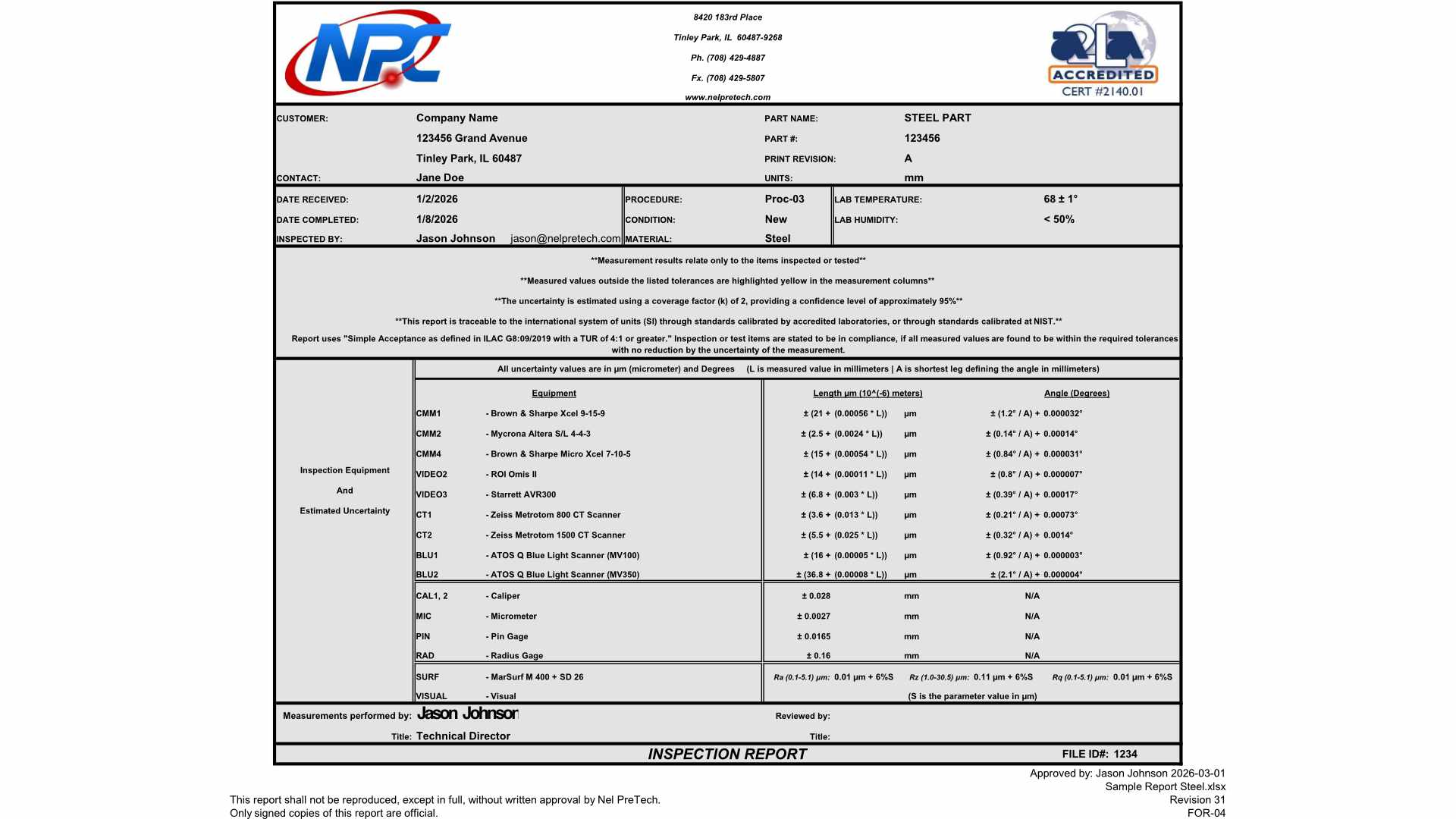
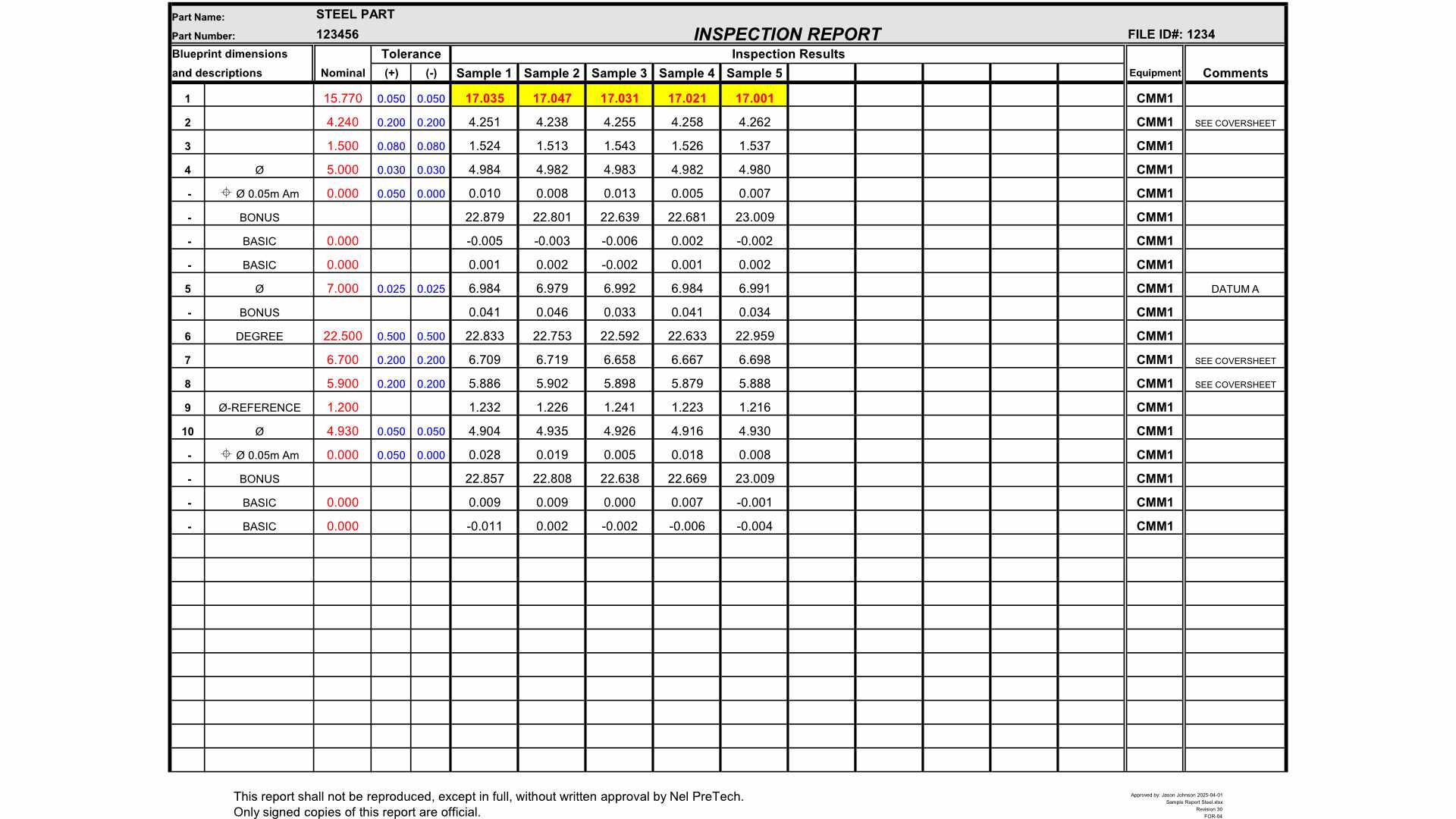
Gathering a measurement is one thing, but knowing what it means takes context.
Here’s a classic example. You have a machined component with a critical hole. It needs to be a certain diameter and sit in a specific position. The diameter measures within tolerance. Good news?
Maybe not. If the hole's position falls outside its positional tolerance, the part may still fail the requirement. And this can happen with molded parts, machined parts, or just about any manufactured part.
A meaningful dimensional layout does more than list numbers in green or red cells. It ties measurements back to engineering requirements, so you know what actually matters for the function of the part.
Before we start measuring, we need to understand the part. We build a roadmap by numbering the print. In that step, we are familiarizing ourselves with the specific features and building the framework of a measurement plan or strategy.
We may review the CAD model to understand unusual or tricky geometry or to clarify or confirm print information. In addition, we look at GD&T callouts, discuss customer expectations and extra requirements like model-based definition (MBD), and note requirements or special fixturing needs.
1. Decide What Gets Measured
An easily accessible outside diameter differs from an internal channel or feature hidden inside.
The inspection requirements may include datum features, profiles, material conditions, and geometric tolerances. They may also identify features that need special attention because of their function or location.
Getting this right up front helps us determine the best equipment and analysis for the job.
2. Get the Alignment Right
How the part is set up for measurement can make a big difference.
GD&T asks you to reference specific datums—that defines how you orient the part and measure everything else.
If the alignment doesn't reflect the engineering definition, the reported measurements may not match reality.
Dimensional inspection requires more than knowing how to operate the measurement tools. It’s about understanding the relationships in the design.
3. Pick the Right Measurement Method
● CMM inspection: A good option for many accessible precision features, including holes, planes, cylinders, slots, and feature locations.
● Vision measurement: Useful for optically accessible tiny features and profiles.
● 3D scanning: Good for surface geometry, CAD comparison, and dimensional deviation analysis.
● Industrial CT scanning: Provides a volumetric dataset that can be used to evaluate hidden and external geometry.
The right tool depends on what needs to be measured, how tight tolerances are, material and complexity, and whether the method chosen can provide suitable results.
Sometimes a conventional measurement is all that's needed. Sometimes the part calls for more.
Some of the most interesting dimensional problems are hidden inside the part -
● internal ribs
● intersecting passages
● complex internal geometry
Industrial CT scanning captures the inside and outside geometry in a 3D volumetric dataset. That data can be interrogated for dimensional characteristics, internal feature relationships, and comparison with CAD.
What can that mean in practice?
A component might have an outside measurement that's within tolerance, but an internal feature could be shifted relative to it. If that relationship matters to the function of the part, we need to evaluate both, and CT makes it possible within the same coordinate reference.
CT is especially powerful for:
● Medical devices and fluid-handling components
● Injection molded parts
● Automotive and aerospace components
● Additively manufactured parts
● Electronics housings
● Complex components or buried features
CT isn't the answer to every inspection problem, but it is a powerful tool that provides more than conventional measurement technologies.
A dimensional layout reports specific measurements compared to requirements: Is that hole really 10.00 ± 0.05 mm? Is the slot in the right spot?
A color map visualizes how the entire surface of the part deviates from CAD. It can show you exactly where and by how much a part warps or drifts.
One gives you specific numerical results. The other helps you highlight the broader trends of geometric variation.
On complex parts, both together can be very helpful.
Nel PreTech covers this visual approach in its article on 3D scan color maps for failure analysis, FAI, and reverse engineering.
Often, we use dimensional layouts to support First Article Inspection (FAI).
FAI is about documenting and verifying that a production part meets all the design specs. The dimensional measurements provide important evidence, but the layout itself isn't the entire FAI.
For aerospace manufacturers working to AS9102, additional documentation and traceability requirements apply. The inspection process must address the applicable characteristics and engineering requirements, along with the required records.
A well-organized layout makes it much easier to check everything off the drawing and keep things moving during FAI.
If you're looking for more information, visit Nel PreTech's First Article Inspection services.
Absolutely, but here’s an important distinction:
One out-of-tolerance dimension flags a local issue. Measurements across several features may reveal a larger pattern:
● A consistent dimensional bias across several features
● Shifts in the location of related features
● Warpage or deformation
● Variation that may be associated with tooling
● Possible machining drift
● Shrinkage or assembly-related movement
● Distortion in an additively manufactured part
Those patterns can point engineers toward areas worth investigating. Additional measurements, process information, or inspection of other parts may be needed to establish the root cause.
Still, the layout provides a useful starting point. The engineering team has data that can help narrow down what happened.
A layout can be useful at several points in a part's life, from initial production through troubleshooting and design changes.
Common applications include:
● Verifying a part against its drawing
● Supporting First Article Inspection
● Evaluating tooling or process changes
● Investigating out-of-tolerance conditions
● Comparing supplier parts
● Supporting incoming inspection and production quality
● Documenting dimensional conformance
● Comparing manufactured geometry with CAD
● Establishing baseline measurements
● Supporting reverse engineering
At Nel PreTech, dimensional inspection starts with understanding which dimensions and results matter to you. Our team determines whether CMM, vision measurement, 3D scanning, industrial CT scanning, or a combination of methods makes the most sense. That distinction matters if you’re looking at tight tolerances, complicated geometry, or internal features.
Depending on the project, our deliverables can include dimensional layouts, GD&T evaluations, CAD comparisons, color maps, wall-thickness analysis, and more.
We match our measurement approach to your part, so you get results you can actually use
Need a layout? Send Nel PreTech your drawing, CAD model, or inspection requirements. Let’s figure out the right measurement plan together.
What is a dimensional inspection layout?
It’s a report that compares chosen measurements from a manufactured part to the dimensions and tolerances in its engineering spec.
What information does a dimensional layout include?
A layout may include nominal dimensions, tolerances, actual measurements, deviations, datum information, GD&T characteristics, inspection methods, and equipment details. The contents depend on the inspection requirements.
Can industrial CT scanning be used for dimensional inspection?
Yes. Industrial CT scanning provides a volumetric dataset that can be used to evaluate internal and external geometry. Suitability depends on the part's material, geometry, scan parameters, and required measurement capability.
What is the difference between a dimensional layout and a color map?
A dimensional layout reports specific measurement results against defined requirements. A color map visualizes geometric deviations across an evaluated surface relative to a reference, such as a CAD model.
Is a dimensional layout the same as a First Article Inspection?
No. A dimensional layout can provide measurement results used in FAI documentation, but FAI also includes broader verification, documentation, and traceability requirements.
Which measurement method is best for a dimensional layout?
It depends on the part and the requirements. CMM, CT scanning, 3D scanning, and vision measurement can each be appropriate for different features, geometries, tolerances, and inspection objectives.

Dave Nelson, co-owner and President of Nel PreTech, has been at the helm of the family-owned metrology and engineering services firm since its founding in May 1993.


You'll find all the detailed service information you need in one brochure.
Download Brochure
Get a quote within 24-hours and keep your project on schedule.
Get a Quote
Our Nel PreTech engineers are ready to get started on your product challenges.
Ask an Engineer
Download the ultimate CT Scanning Buyer's Guide to improve understanding, time, and efficiency in your scanning needs. Over 50 Pages of useful data and case studies.
Download Now