Learn how to find internal voids in injection-molded parts using industrial CT scanning, including defect location, measurement, and analysis.
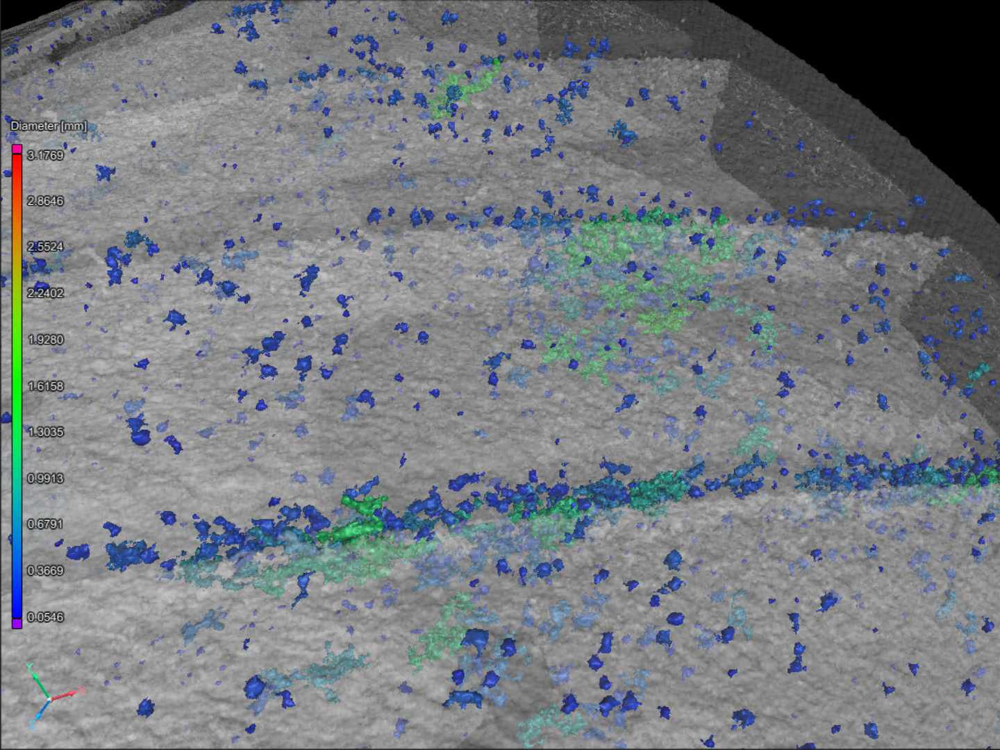
Most things contain some amount of missing material or cavities, also known as porosity. The size, location, and volume are what’s important to know. Cutting the part open to find defects could work. It can also be counterproductive by destroying evidence. And it may not tell you whether the defect will show itself in the entire production run.
So how do you find internal voids in injection-molded parts?
Industrial X-ray computed tomography (CT) scanning is a reliable, nondestructive way to see and measure what's inside a molded part.
Locating defects is the first step. The next step is finding out the type of defect it is, how large it is, where it is, and whether it can affect how the part functions.
The molding process can introduce internal voids in various ways.
Common causes:
Defect locations become important to engineering teams.
A small cavity in a nonfunctional region of the part may be of little concern. The same size void near a critical feature, sealing surface, snap fit, threaded insert, or load-bearing section could cause issues.
For injection molded parts, the defect holds important clues, but that may only be the start.
The surrounding geometry can show other clues leading to the potential cause of a void.
Picture a molded component with a thick boss. The boss is connected to a relatively thin wall. Maybe the boss cools differently from the surrounding material. If CT reveals a void concentrated within that thicker region, the location becomes important to the investigation.
The same applies to:
Locations and other details around a defect can be just as important as size. An engineer may need to figure out whether the void is centered, close to a surface, associated with a thick area, or near a functioning feature.
Void Detection and Porosity Analysis Are Not Always the Same Thing
The terms void and porosity can sometimes mean the same thing when discussing industrial CT data. However, they aren’t always the same measurement or analysis.
One of the most important distinctions is where the space exists. Is it completely enclosed within the material?
When Nel PreTech performs a porosity analysis, the analysis is focused on encapsulated porosity. This is a bubble or void that is surrounded by material.
The analysis can be used to characterize the internal voids, including information such as:
This is helpful when an engineering team wants to determine whether internal voids could affect the strength or functionality of a part. Especially near a critical feature or structural area.
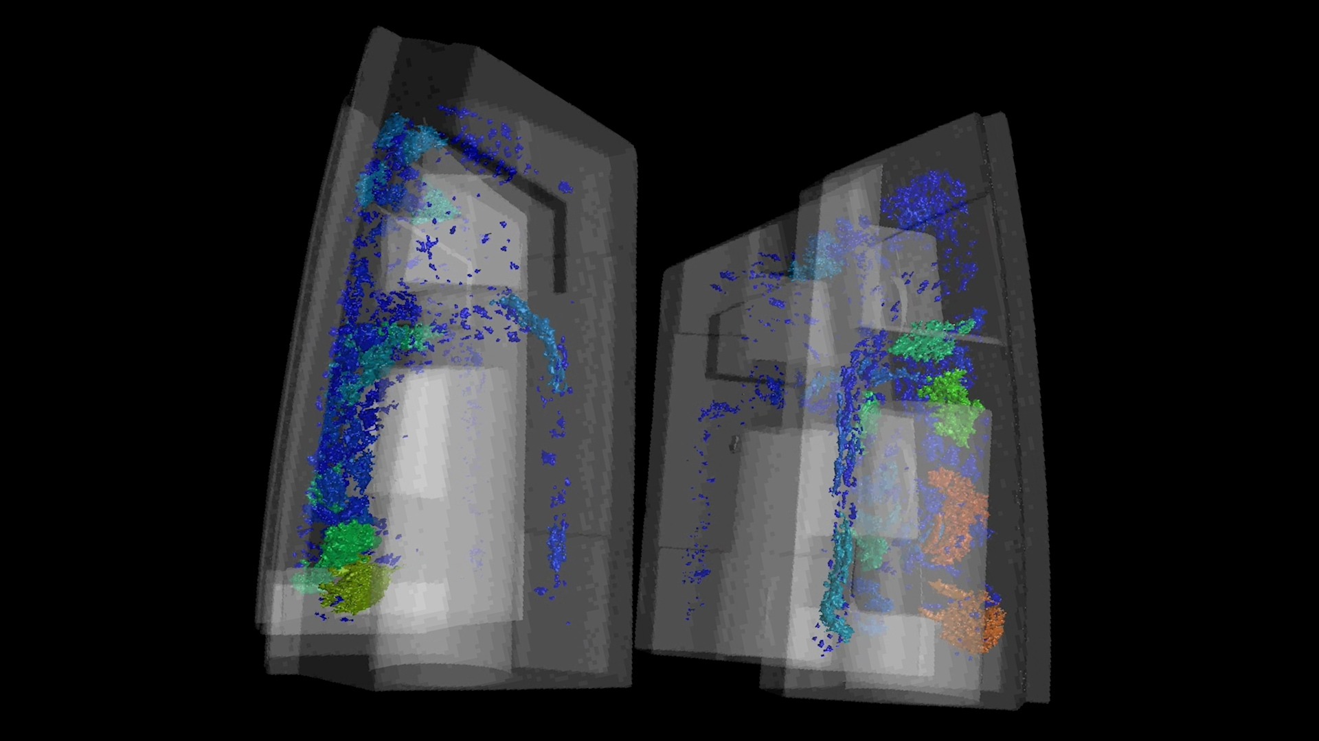
Consider a piece of Swiss cheese.
The holes that are completely enclosed within the material are one type of condition. A surface opening isn’t just an empty pocket trapped inside. It’s exposed, and analysis is handled differently. When you see a divot or any feature that connects to the outside, you end up with potential leak paths, visible internal structures, or even weak points in the part. Problems like these need a different approach.
Take foam structure analysis, for instance. It helps spot areas open to the surface, not just hidden pockets. That difference matters. A part might have minimal encapsulated porosity but still suffer from serious surface-connected defects. So you can’t treat every void the same.

The Size of the Defect Has to Match the CT Resolution
There is another important question when planning porosity or void analysis:
How small does the defect need to be?
This means you’re not looking for ALL the pores; you’re considering the resolution of the CT scan instead.
Our general rule for analysis: CT resolution should be approximately one-third of the minimum feature size you need to analyze.
For instance, if the requirement is to analyze porosity at 100 µm or larger, a resolution of approximately 33 µm provides about three voxels across a 100 µm feature.
That three-voxel relationship provides a strong basis for quantitative analysis.
This does not mean that a CT scan at a lower resolution will make every feature below 100 µm disappear.
Smaller features may still show up, but visibility doesn’t mean you can perform quantitative analysis.
If the pore is too small relative to the voxel size, there may not be enough information to measure its volume, size, location, or other characteristics.
That is why the required minimum pore or void size should be established before the inspection whenever possible.
This is where collaboration with the customer becomes important.
If you’re just trying to understand what’s inside an unfamiliar part, the initial goal may be exploratory:
Let's scan it and see what we can find.
In that scenario, the scan can be a starting point. If the initial CT data shows something that warrants further investigation, then inspection can be refined around those findings.
But if the goal is to qualify a product against a specification or tolerance, the requirements need to be more specific.
For example:
These requirements directly determine the CT scan resolution and analysis capability.
The inspection should be designed around the engineering requirement, not around whatever resolution seems convenient.
That happens.
In a perfect world, the customer comes to the lab with inspection requirements already defined. But in reality, the engineering team may not know the minimum pore size, or may not have access to all the information needed to establish that requirement.
I look at CT inspection as a collaborative process.
Part of our responsibility is to ask the questions that help determine what needs to happen.
Sometimes that conversation gives us everything we need to define the inspection.
Other times, we have to establish a reasonable starting point without overpromising what the data can prove.
For example, if our customer doesn't know the minimum pore size, we may start with a resolution that provides useful visual information.
If nothing significant appears, that may answer the immediate question.
If we see internal features that need analyzing, the next question becomes whether the current resolution provides enough information. If it doesn't, we may need to adjust the resolution or inspection approach.
The key is not to imply a level of detection or analysis the data cannot support.
Industrial CT collects X-ray projections as the part rotates on a 360-degree stage. It rebuilds those projections into a three-dimensional dataset.
That dataset can be sliced through virtually. No physical cutting needed.
Depending on the inspection requirements and CT resolution, the same dataset can support these deliverables:
An important note: visualizing a feature is different than analyzing it quantitatively.
A CT image may show that something is present.
Quantitative analysis needs enough information from the dataset to determine size, volume, and location.
Establishing resolution up front is the foundation for a good CT experience.
What About Destructive Sectioning?
Cutting a molded part open has its uses.
It’s straightforward, inexpensive, and sometimes exactly what the engineer needs.
Beware of these limitations:
Industrial CT is a perfect alternative when preserving the part and all of its geometry matters.
Different NDT methods have different strengths.
Ultrasonic inspection, for example, can be good for finding certain internal discontinuities. But its effectiveness can be hindered by material, geometry, access, defect orientation, and the inspection objective.
Computed tomography’s strength is when the requirement is to visualize and measure complex internal geometry in three dimensions.
The right inspection method depends on the engineering question.
Your starting point should be:
What do we need to know about the part?
Then choose the inspection method that can answer that question reliably.
Not by itself.
CT can show you what’s inside the part. It can show you where the void sits and how it relates to the geometry around it.
Determining the why requires engineering interpretation.
For an injection-molded component, that may involve looking at:
For example, if CT scans show a recurring void in the center of a thick section, that finding may support an investigation into volumetric shrinkage and cooling behavior.
The CT scan does not replace process knowledge. It gives the engineering team better evidence to work with.
A great application is comparing parts rather than inspecting a single part alone.
Imagine a molding team has a component that is giving them trouble during assembly.
The outside dimensions are within tolerance.
The molding process checks out as normal.
But CT inspection of good and bad samples may reveal a difference in the structure inside.
Perhaps the failed parts consistently contain a larger void near a critical feature.
Now the investigation has momentum.
The team can now correlate the CT findings with molding conditions, material lots, cavity locations, cooling behavior, or other production variables.
Yes, depending on the inspection objective.
A single part may be enough to investigate an unexpected defect.
For process development or failure analysis, however, comparing multiple parts can provide considerably more information.
For example, CT data can be used to compare:
The goal isn’t to generate more data.
It’s to determine whether internal conditions change in a way that can be linked to the engineering problem.
This is where I recommend getting specific.
Before scanning, identify the engineering question.
For example:
If the minimum defect size or acceptance criteria are known, they should be communicated before scanning. They can directly affect the required CT resolution and the analysis that can be performed.
If they are not known, that should be part of the conversation with the CT lab.
Clearly defined questions and desired outcomes create a more confident inspection design.
What Information Does the CT Data Provide?
Depending on the application, the same CT dataset can support several types of analysis.
Locate and characterize encapsulated voids, porosity, inclusions, and other internal anomalies.
Evaluate the thickness of molded walls, ribs, bosses, and other features.
Compare the scanned geometry against nominal CAD data.
Measure internal and external features that may otherwise be difficult or impossible to access.
Inspect components containing inserts or assembled features without disassembling them.
Compare failed and functional components to identify differences in internal structure.
That flexibility is one of the reasons CT has become such a valuable tool for complex molded components.
I've been involved with dimensional inspection and CT applications long enough to know that the most interesting part of an inspection is rarely the picture itself.
A CT scan can produce an impressive image of a defect.
But an engineer usually needs to answer a much harder question:
Does this defect matter?
That requires understanding the part's function, material, geometry, tolerances, manufacturing process, and failure mode.
A void in a cosmetic housing may be acceptable.
A void beneath a sealing surface may not be.
A cavity inside a thick boss may tell you something important about the molding process.
And a surface-connected opening can present an entirely different concern from an encapsulated pore because it may create a path through the material.
The technology gives us visibility.
Engineering judgment gives that visibility meaning.
Industrial CT scanning is a nondestructive way to inspect hidden regions while preserving the complete three-dimensional geometry.
A successful CT inspection depends on the required defect size, resolution, type of analysis, and acceptance criteria.
For porosity analysis specifically, the distinction between encapsulated internal porosity and surface-connected openings is important. And when a minimum pore size needs to be quantitatively analyzed, the CT resolution needs to be appropriate for that requirement.
When a molded component is suspected of having an internal defect, the objective should be to answer:
What are we looking for? How small does it need to be? Where is it? Can we measure it? And does it affect the way the part is supposed to work?
Those are the questions that turn CT data into meaningful information.
At Nel PreTech, that's how we approach CT inspection: not just looking inside a part, but working with engineers to understand what the inspection needs to prove and what the data actually tells us.
Have a molded component that isn't behaving as expected? That's usually a good reason to look inside.

Dave Nelson, co-owner and President of Nel PreTech, has been at the helm of the family-owned metrology and engineering services firm since its founding in May 1993.


You'll find all the detailed service information you need in one brochure.
Download Brochure
Get a quote within 24-hours and keep your project on schedule.
Get a Quote
Our Nel PreTech engineers are ready to get started on your product challenges.
Ask an Engineer
Download the ultimate CT Scanning Buyer's Guide to improve understanding, time, and efficiency in your scanning needs. Over 50 Pages of useful data and case studies.
Download Now