Learn how blue light scanning works, what part sizes and geometries can be scanned, and when to use CT, CMM, or 3D scanning services.

Non-contact metrology is now common in manufacturing because engineers need faster dimensional data, full-surface inspection, and usable digital models. Blue light scanning captures dense external surface geometry without touching the part, making it useful for inspection, CAD comparison, and reverse engineering.
The practical questions are more specific. What part sizes can be scanned? What resolution is realistic? Will shiny metal, clear plastic, deep pockets, or tight-tolerance features scan correctly? The answer depends on geometry, surface condition, field of view, tolerance requirements, and inspection objective.
Blue light scanning is a structured blue light scanning method. A projector casts a known blue light pattern onto a part surface. The pattern is observed using cameras. Specialized software uses optical triangulation to compute X, Y, and Z coordinate data. The output is a point cloud, which can be turned into a mesh, compared to CAD, or used for reverse engineering.
In a white light vs. blue light scanning comparison, both are optical surface measurement methods. Blue light is commonly preferred in industrial metrology because its shorter wavelength supports sharper pattern projection and can reduce sensitivity to some ambient lighting.
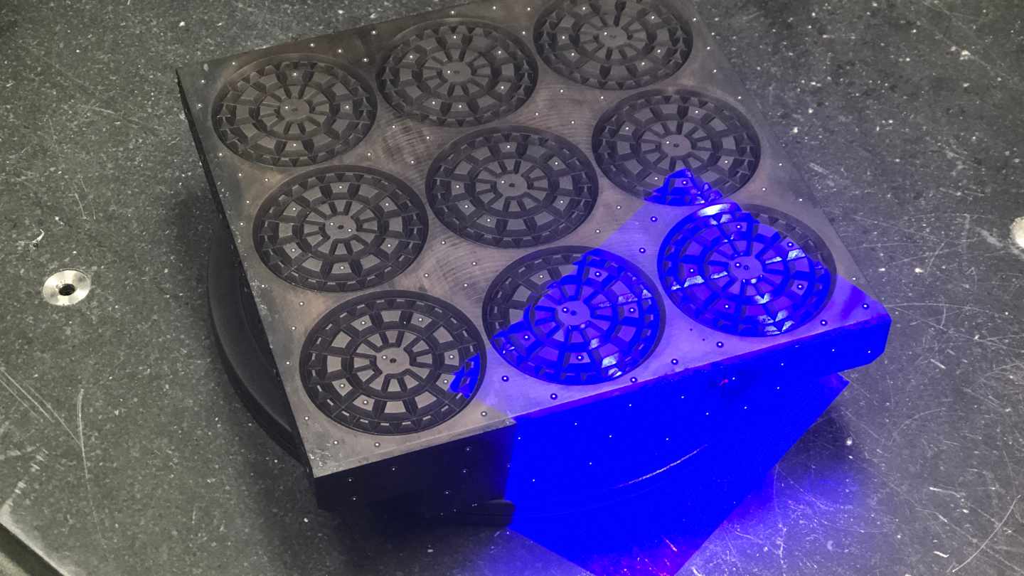
Blue light scanning is scalable, but not unlimited. Scanner configuration, lens selection, calibration volume, fixturing, and scan strategy all affect results.
Small precision components are a strong fit when external detail matters. Medical device parts, electronic housings, aerospace hardware, molded parts, and machined features can often be scanned using smaller fields of view and higher-resolution setups.
Typical applications include medium-sized industrial components. Castings, automotive parts, mold tooling, and housing and assemblies can be scanned for deformation, first article inspection, reverse engineering, and CAD comparison.
Large components can also be scanned, but the workflow changes. Machine frames, structural assemblies, tooling, and industrial equipment usually require multiple scan positions, registration targets, photogrammetry, or stitching. As size increases, accuracy depends more on registration strategy, environmental control, and calibration.
Resolution and accuracy are not the same. Resolution describes point density and small surface detail. Accuracy describes how close the measured data is to the true part geometry or a traceable reference. This distinction matters for dimensional inspection services, GD&T inspection services, and CAD-to-part reporting.
A smaller field of view can provide higher point density, but it may require more scans. A larger field of view captures more area quickly, but may reduce fine-feature visibility. Inspection planning should start with the measurement objective.
Blue light scanning performs best on visible external surfaces. Complex freeform shapes are often ideal because the scanner captures dense surface geometry more efficiently than limited manual measurements.
Examples include castings, turbine parts, ergonomic products, prototype housings, molded parts, medical device exteriors, and additive-manufactured surfaces. Organic and sculptured geometries also make good candidates as optical scanning can be used to detect curvature and surface transitions.
Reverse engineering services are another major use case. When legacy parts, tooling, or prototypes lack usable CAD, blue light scanning can generate surface data for mesh creation, CAD reconstruction, and dimensional comparison.
Blue light scanning is a line-of-sight technology. It cannot measure what the cameras cannot see. Deep internal channels, enclosed cavities, buried defects, and hidden assembly interfaces are usually better suited for industrial CT scanning, which captures internal and external geometry using X-ray data.
Data problems can also occur with reflective or transparent surfaces. Sometimes the projection pattern is reflected or transmitted by polished metals, glass, clear plastics, and molded parts with glossy surfaces, rather than returning useful image data. Temporary scanning sprays, matte coatings, controlled lighting, and fixturing may improve results, but surface preparation must be compatible with inspection requirements.
Extremely tight-tolerance features may still require CMM inspection services. CMMs remain valuable for datum structures, bore positions, precision planes, critical distances, and controlled probing strategies. In many projects, blue light scanning and CMM inspection are complementary rather than competing methods.
Blue light scanning is best for fast capture of external surfaces, complex geometry, CAD comparison, deformation analysis, and reverse engineering. White-light scanning uses similar structured-light principles, but can be more sensitive to environmental effects. CMM inspection is best for critical tolerances, datum-based measurements, prismatic features, and formal dimensional reporting. Industrial CT scanning is best when the required data is internal, including hidden geometry, voids, porosity, wall thickness, and assembly accuracy.
Manufacturers should select scanning technology based on part size, material type, surface finish, tolerances, internal versus external features, and inspection objective. Reverse engineering may prioritize full surface capture. First article inspection may require GD&T reporting and datum alignment. Failure investigation may require internal defect analysis.
If you are evaluating how to measure a part, validate a design, or solve a quality issue, the fastest path forward is to speak directly with a metrology team that can assess your specific requirements. At Nel PreTech, 3D scanning services, dimensional inspection services, industrial CT scanning, CMM inspection services, and reverse engineering services are approached as part of the same measurement decision. Contact our team of experts to review your part, discuss your inspection goals, and determine the most effective measurement strategy for your application.

Chad is a 3D Digital Designer at Nel PreTech Corporation. He transforms raw scan data into precise, manufacturable CAD models. He’s taken on legacy parts with no drawings and complex shapes with an artist’s eye. As a sculptor, Chad possesses a rare intuition that helps him solve complex design puzzles.


You'll find all the detailed service information you need in one brochure.
Download Brochure
Get a quote within 24-hours and keep your project on schedule.
Get a Quote
Our Nel PreTech engineers are ready to get started on your product challenges.
Ask an Engineer
Download the ultimate CT Scanning Buyer's Guide to improve understanding, time, and efficiency in your scanning needs. Over 50 Pages of useful data and case studies.
Download Now